A Comprehensive Guide to Understanding Wall Outlet Circuit Diagrams
Circuit diagrams are essential tools when it comes to electrical wiring and can be found in homes, offices, and commercial buildings. Going beyond simply providing information on the flow of electricity, these diagrams represent the puzzle pieces of a greater system and provide valuable insight into how the electricity is used or shared. Although it may seem intimidating for someone without the relevant experience, understanding wall outlet circuit diagrams is made possible with the right resources and background information.
Nowadays, anyone with access to the internet can view and learn about wall outlet circuit diagrams with relative ease. From providing information on wiring components to offering expert opinion on the installation and troubleshooting of electrical systems, this type of resource is invaluable to anyone who wants to make sure their building or residence is up to code and safe. Here you will learn what a wall outlet circuit diagram is and how it can be read and understood, as well as the importance of hiring a qualified electrician to help keep your wiring up-to-date.
What is a Wall Outlet Circuit Diagram?
A wall outlet circuit diagram is a drawing that provides a descriptive roadmap of the electrical outlets in a building. It shows the physical locations of all the outlets, as well as how they are connected in a series, allowing easy identification of individual outlets and the amount of electricity each one is receiving. These diagrams are especially helpful for identifying the wiring requirements for particular outlets, as well as for troubleshooting any problems that may arise.
In addition to providing detailed descriptions of the power distribution of a building, these diagrams also offer a visual representation of the switch boxes and lighting outlets that are often connected to several outlets within the same room. By being able to quickly identify these peripheral devices, it’s possible to pinpoint where certain fixtures are located and determine which outlets are powered by them, making complex installations easier to manage.
The Importance of Professional Guidance
Since wall outlet circuit diagrams can be quite complex, it’s important to hire a professional electrician whenever dealing with wiring issues. Though there are many resources available to assist with diagnosing and fixing simple problems, attempting to tackle a major project like rewiring a building or replacing a breaker box without the help of a trained professional can result in safety issues, as well as property damage.
When it comes to proper installation of wiring, electrical codes must be followed to ensure the safety of everyone using the building. Qualified electricians are familiar with national and local regulations, allowing them to complete the job efficiently and accurately. Additionally, most electricians are knowledgeable about other aspects of a building’s wiring, such as security systems, ventilation, and power distribution. Hiring a professional is the best way to make sure that the wiring in a building is up to date and meets the requirements of the local code.
Conclusion
Wall outlet circuit diagrams are incredibly useful when it comes to understanding the distribution of power in a building. By understanding the basics of how to read a diagram and locate areas of concern, an individual can quickly and easily identify potential problems and discuss solutions with an electrician. Remember, it’s always best to hire a qualified professional to handle any electrical wiring job, as doing so will help ensure that all projects are completed up to code.
Electrical Power Socket Connection Diagram And Wiring Procedure Etechnog

Wiring Diagrams

Ceiling Fan Wiring Diagrams
/tips-for-wiring-outlets-and-switches-1824668-hero-5c1c9847042c4caa9397bf5caa3d9661.jpg?strip=all)
How To Wire Electrical Outlets And Switches

Electrical Drawings And Schematics Overview

How To Wire A Standard Light Switch Hometips
Multiple Receptacle Outlets Wiring Diagrams Do It Yourself Help Com

Solidworks Electrical Schematic

Electrical Drawings And Schematics Overview

Switched Outlet Wiring Diagrams

Electrical Outlet Wiring Diagram Radial And Ring Mains Electronics Engineering

Rewire A Switch That Controls An Outlet To Control Overhead Light Or Fan

Simple Radial Circuit
/wiring-electrical-receptacle-circuits-through-a-receptacle-1152787-hero-8d90cda18cdd485db90dc3122edd4725.jpg?strip=all)
Wiring An Outlet In The Middle Of A Circuit
Gfci Outlet Wiring And Connection Diagram Etechnog

Your Home Electrical System Explained

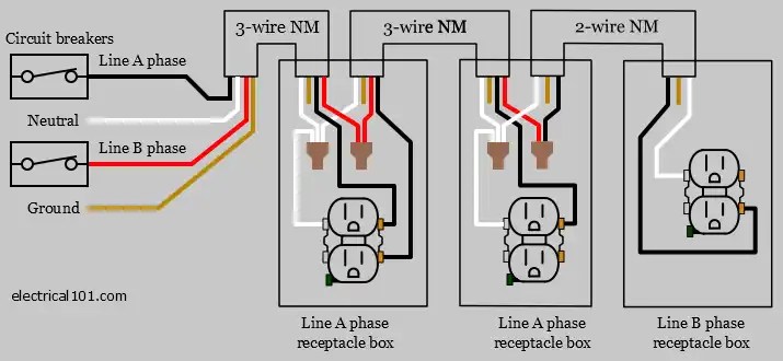
Multiwire Branch Circuit Electrical 101

Electrical Outlet Wiring Diagram Radial And Ring Mains Electronics Engineering
:max_bytes(150000):strip_icc()/tips-for-wiring-outlets-and-switches-1824668-06-0282c26178324283beb8d2701f1cc424.jpg?strip=all)
How To Wire Electrical Outlets And Switches


