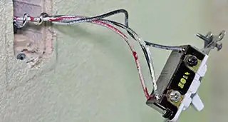
The Basics of Three Way Switch Wiring Diagrams
When it comes to wiring a home, the task can be downright intimidating for some homeowners. Understanding the basics of the three-way switch wiring diagram can make the job easier. A three-way switch wiring diagram is a type of electrical diagram that explains how to wire a household circuit in which two or more lights operate from one switch.
Three-way switch wiring diagrams can be complicated if you don't understand the fundamentals. But with a bit of practice, you can easily wire up your home using these diagrams. By following the guidelines outlined here, you will have no trouble wiring up the switches correctly.
Understanding the Basics of Three-Way Wiring
Before we start discussing how to wire a three-way switch, let's review the basics of wiring a two-way switch. A two-way switch has two terminals, the common (COM) and the traveler (TRV). It works by energizing one side or the other depending on which way the switch is turned. When the switch is off, it does not energize either side.
In contrast, a three-way switch is designed to allow two lights to be controlled by one switch. It has three terminals: the common (COM), the traveler (TRV) and the ground (GRD). To wire a three-way switch, the COM and TRV should be connected to the appropriate wires and the GRD should be connected to the ground wire. The use of a 3-way switch allows two lights to be operated independently by means of a single switch.
Installing the Three-Way Switches
Once you've gathered the materials and tools needed to install your new three-way switch, you'll need to identify the proper locations for each switch. In order for the switch to work properly, it must be installed in the correct position. Typically, the common terminal of the switch should be located on the left, with the traveler terminal on the right. The ground terminal should be on the bottom.
Using an approved wiring diagram, connect the appropriate wires to the terminals of the switch. The black wire is designated as the hot wire and is typically used for the common terminal. The white wire is the neutral wire and should be connected to the traveler terminal. The ground wire should be connected to the ground terminal.
Understanding the Wiring Diagrams
Once the switches are installed, you'll need to interpret the wiring diagram to make sure you wired them correctly. Most three-way switch wiring diagrams feature several columns of numbers and symbols. These represent the circuit components and their function, respectively. The left column typically represent the source power, while the right column represent the light, fan or outlet that the switch controls.
The top row of numbers in the wiring diagram indicates the hot wires. The middle row represents the neutral wires and the bottom row indicates the ground wires. Once you have identified the circuit components, the next step is to connect the wires according to the diagram. Make sure you follow the directions carefully to ensure that the switch is properly wired.
The Benefits of Three-Way Switch Wiring Diagrams
Three-way switch wiring diagrams provide an easy way to wire a home circuit and make sure that all of the wires are correctly connected. They allow homeowners to understand the function of each switch, so they can properly install the circuit. They also help identify any potential problems in the wiring, such as open circuits or reversed wires. Understanding the basics of three-way switch wiring diagrams can save time and money when wiring a household circuit.
How To Wire Three Way Switches Part 1
3 Way Switch Wiring Diagrams Do It Yourself Help Com
3 Way Switch Wiring Diagrams Do It Yourself Help Com

3 Way Switch Wiring Electrical 101
How To Wire Three Way Switches Part 1

3 Way Switch Wiring Diagram
3 Way Switch Wiring Diagrams Do It Yourself Help Com

Mep Ep 79 Dueling Opamp Inputs Macrofab
Working Together Works

3 Way Switch Wiring Electrical 101
3 Way Switch Wiring Diagrams Do It Yourself Help Com
How To Wire Three Way Switches Part 1

3 Way Switch Wiring Electrical 101

Wiring A 3 Way Switch

Traveler Wires 3 Way Switch Big Ing Hit A 68 Www Iraqi Datepalms Net

3 Way Switches Electrical 101

How To Wire A 3 Way Switch Wiring Diagram Dengarden

How To Wire A 3 Way Light Switch Diy Family Handyman


