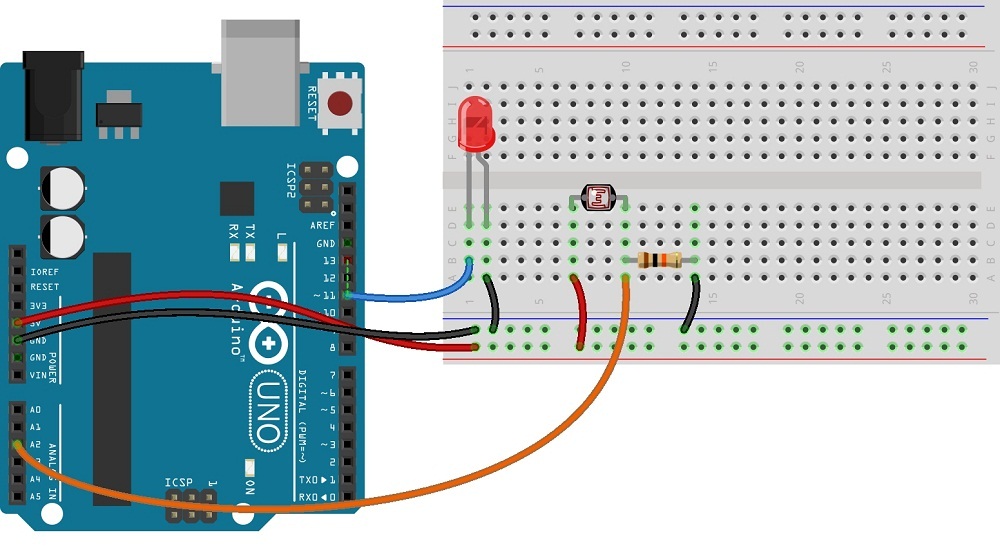
Understanding the Different Parts of an LDR Pin Diagram
The Light Dependent Resistor (LDR) pin diagram is an essential part of any electronic circuit. It is an essential component of a variety of circuits, such as light sensors and photocells. Understanding how an LDR works is key to maximizing its potential in a circuit. In this article, we explore what components make up an LDR pin diagram and explain how it functions.
An LDR pin diagram consists of five pins, each with its own purpose. These pins interact with the surrounding environment to detect and measure light. The five pins are referred to as "common," "positive," "negative," "clockwise," and "counterclockwise." By understanding each individual pin's function, you can use the LDR effectively in a given circuit.
Common Pin
The common pin is the middle pin of the five on the LDR. This pin is typically connected to ground, or to the negative power supply, depending on the type of circuit being used. It's main purpose is to provide a reference voltage, so that current will only flow when the positive and negative pins are at different voltages.
Positive and Negative Pins
The positive and negative pins are located on either side of the common pin on the LDR. The purpose of these pins is to supply power to the LDR when required. When the positive pin is supplied with a higher voltage than the negative pin, current will flow through the LDR. This will cause the resistance of the element to decrease and allow current to flow.
Clockwise and Counterclockwise Pins
The clockwise and counterclockwise pins are located at the top and bottom of the LDR, respectively. These pins control the direction in which current flows through the LDR. When the clockwise pin is supplied with a higher voltage than the counterclockwise pin, current will flow in a clockwise direction. Conversely, when the counterclockwise pin is supplied with a higher voltage than the clockwise pin, current will flow in a counterclockwise direction.
Conclusion
An LDR pin diagram consists of five pins – common, positive, negative, clockwise, and counterclockwise. Each pin serves a unique purpose and must be considered when setting up an LDR in a circuit. By understanding how each pin functions, you can use an LDR effectively and efficiently in a circuit.

Ldr Engineering Buildcircuit Com

Circuit Diagram Of Ldr Scientific

Light Dependent Resistor Ldr Working Principle And Its Applications

Ldr Photoresistor Pinout Working Applications Datasheet

Photocell Ldr Sensor With Arduino Theorycircuit Do It Yourself Electronics Projects

Light Dependent Resistor Circuit Diagram Types Working Applications

Light Dark Activated Relay

How To Use Photoresistor Ldr With Arduino Uno

Ldr Photoresistor Pinout Working Applications Datasheet

Automatic Street Light Controller Using Ldr

Ldr Circuit Diagram Darkness Sensor

Arduino Light Sensor Circuit Using Ldr

Ldr Photoresistor Pinout Working Applications Datasheet

Darkness Detector With Beep Alarm Using Ldr And 555 Timer Lindevs

Light Operated Relay Circuit Using Ldr Photoresistor Electronics Area

Light Dependent Resistor Ldr Or Photoresistor What Is It Electrical4u

Dark Sensor Ldr Darkness Senor Circuit

How To Use Ldr Sensor In Proteus The Engineering Projects

Ldr Circuit Diagram Build Electronic Circuits

Diy A Simple Automatic Street Light Controller Circuit
