Uncovering the Mysteries of a Clock Circuit Diagram
Have you ever wondered what goes into the design of a clock circuit? Well, if you have, then you’re in for a treat. Here, we’ll be taking a deep dive into the intricate details of a clock circuit diagram to uncover its most intriguing mysteries. From its components and connections to its basic operation and uses, this guide will provide you with important information that you need to know about the design of these circuits.
Before diving into more complex topics such as the timing and synchronization of a clock circuit, it is vital to have an understanding of the basic components that make up this essential circuitry. The clock circuit diagram consists of three main components which are each designed to perform specific tasks: the clock source, the pulse generator, and the oscillator. Each of these components works together to ensure the accuracy of the clock signal and its timing.
Understanding the Clock Source
The clock source is an electronic component which outputs a periodic signal. This signal acts as a reference for the other components in the circuit and determines the frequency of their operations. Its frequency is usually determined by either crystal oscillator or quartz oscillator and can range from a few hertz to several gigahertz depending on the application.
There are many different types of clock sources which can be used in a clock circuit, including analog, digital, and phase-locked loop (PLL) clock sources. Each type of clock source provides different levels of accuracy and stability in terms of the timing of the output signal. Additionally, they may also have different power requirements and cost considerations, so it is important to take these into account when selecting a clock source.
Exploring the Pulse Generator
The pulse generator is an electronic component which generates periodic pulses from the clock source, which are then used to drive the other components of the circuit. These pulses can be generated in a variety of ways, including analog and digital circuits. A common type of pulse generator is known as the astable multivibrator, which is used to provide a continuous stream of pulses with a given period. Other types of pulse generators include the monostable multivibrator, which produces only a single pulse for each clock cycle, and the bistable multivibrator, which produces two pulses per clock cycle.
When selecting a pulse generator, it is important to consider the frequency stability, power requirements, cost, and accuracy of the device. Additionally, it is also important to understand how the generator handles various types of clock signals, as some may not be suitable for certain applications.
Discovering the Oscillator
The oscillator is the last component of the clock circuit, which performs the task of synchronizing all of the other components. In a typical circuit, the oscillator is connected to the signal from the clock source and the output from the pulse generator. The oscillator then compares the two signals and adjusts the timing of its own signal accordingly until the two signals are synchronized.
Oscillators come in a variety of types, including analog, digital, and hybrid types. It is important to select the right type of oscillator for your application, as each type has its own advantages and disadvantages. Additionally, the power requirements and cost of the oscillator should also be taken into consideration.
Understanding the Usages of a Clock Circuit Diagram
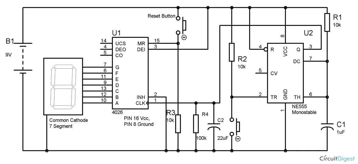
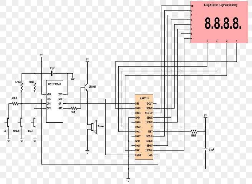
A clock circuit diagram is a schematic representation of a clock circuit which shows how the various components are connected and interact with each other. This diagram is typically used to assure that the clock circuit is operating correctly and is useful for troubleshooting any issues that may arise. Additionally, it can also help engineers to quickly identify any potential problems that may exist within the circuit.

Auto Snooze For Digital Alarm Clocks Electronics You

Digital Clock Alarm Based On The Lm8560
Galactic Electronics Projects 12 Hour Digital Clock
Circuit Diagram How Digital Clocks Work Howstuffworks

Circuit Barkeng Mad

7 Segment Display Counter Circuit Using Ic 555 Timer

Digital Clock Circuit With Seconds And Alarm Time Display

Digital Clock

جزر البحر تلغراف تنشيط Led Clock Diagram Love2tour Com
جزر البحر تلغراف تنشيط Led Clock Diagram Love2tour Com

Digital Clock Without Microcontroller

How To Make A Simple Digital Clock Circuit Explained

Timer Electronic Circuit Countdown Schematic Diagram Png 800x600px 555 Ic Clock

Lm8361 Datasheet Pdf Clock Circuit Ic Sanyo Electric

Nixie Clock Without Mcu

Ds1302 Real Time Clock Circuit Pinout And Datasheet Easybom

Digital Timer Circuit Diagram And Its Working Principle

Lm8365 Digital Clock Circuit Board Eleccircuit Com

12h 24h Digital Clock Circuit Online Electronics Course

