Understanding Circuits Schematic Diagrams: A Comprehensive Guide
Circuits schematic diagrams are powerful tools used to accurately explain the function of electrical and electronic materials and components. Whether you're an engineer, hobbyist, or layperson, understanding circuits schematic diagrams is essential for safe and effective electrical works. This guide provides a comprehensive overview of circuits schematic diagrams – what they are, their features and uses, and ways to draw them.
What Is a Circuits Schematic Diagram?
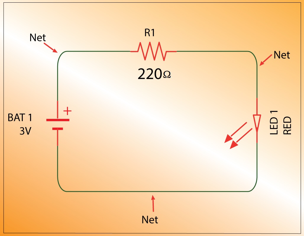
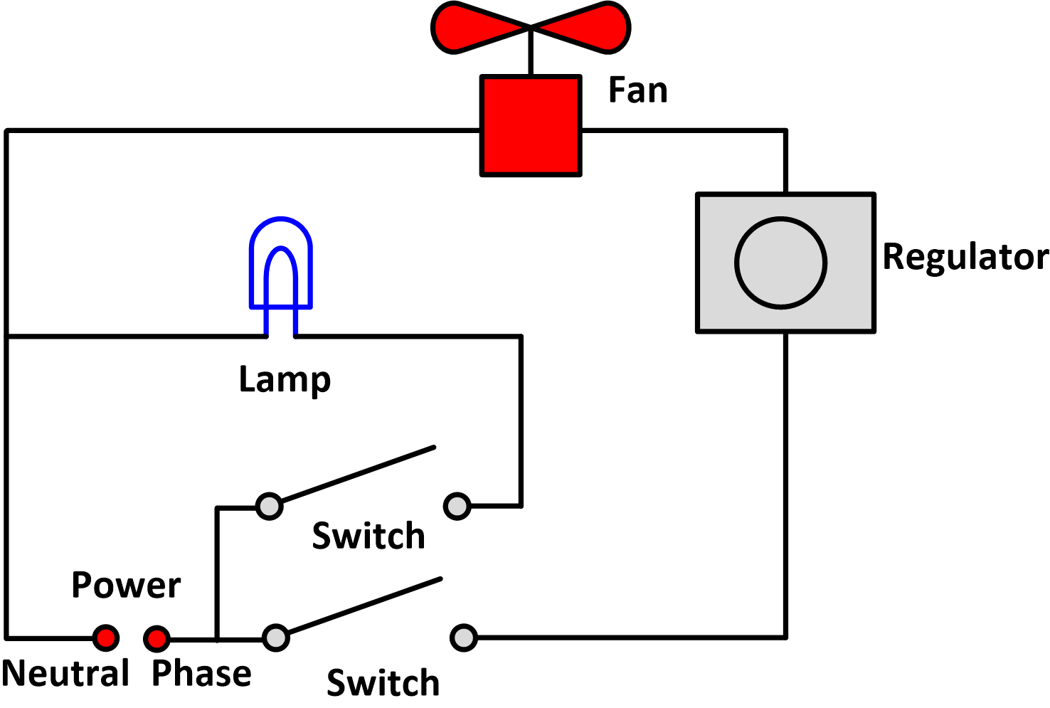
A circuits schematic diagram is an electric circuit diagram that utilizes symbols to represent various electric and electronic components, such as resistors, capacitors, inductors, switches, relays, transistors, etc. These diagrams are easy to read and provide a precise visual mapping of the circuit’s configuration. They are used by many professionals in the electrical engineering field, particularly in the design, development, and manufacture of electric/electronic components and systems.
Features and Uses of Circuits Schematic Diagrams
Circuits schematic diagrams are most often used during the development phase of electrical works, providing engineers with an efficient and precise means of testing the behavior of a system. In addition to the visual map of the circuit’s configuration, these diagrams also provide useful information about the power sources, voltages, currents, and safety regulations of the circuit. In addition, these diagrams can be used to troubleshoot problems, identify short circuits, and help pinpoint potential weak spots in the system.
Drawing Circuits Schematic Diagrams
Drawing circuits schematic diagrams is a tricky task and requires a good knowledge of the electrical theory and principles. To begin, the designer needs to study the design of the circuit and drawn a complete schematic diagram. Next, the designer needs to use the correct symbols to represent the components. The diagrams must also include labels, indicating specific voltages, polarities, and currents, as well as other required technical specs. Finally, the designer needs to review the diagram and make sure it accurately reflects the circuit’s configuration.
Benefits of Using Circuits Schematic Diagrams
Circuits schematic diagrams offer numerous benefits for both the engineer and the user. For one, these diagrams provide a visual representation of the circuit, making it much easier to identify potential weak spots or issues. Furthermore, they provide detailed information about the voltage, current, and safety regulations of the circuit. Finally, they can be used to test the system, diagnose problems, and identify short circuits, making them an invaluable tool for electrical engineering.
Conclusion
Circuits schematic diagrams are indispensable tools used by professionals in the electrical engineering field. By utilizing symbols to represent various electric and electronic components, they provide a comprehensive overview of the configuration of a circuit. Furthermore, they provide useful information about the power sources, voltages, currents, and safety regulations of the circuit. With these diagrams, engineers can test the system and accurately troubleshoot and diagnose problems.

How To Create Circuit Diagram

Pcb To Schematic Diagram Printed Circuit Board Manufacturing Assembly Rayming

Circuit Diagram Softe

Top 10 Best Circuit Diagram Makers Of 2021 My Chart Guide

Physics Tutorial Circuit Symbols And Diagrams

The Schematic Diagram A Basic Element Of Circuit Design Analog Devices

What Is The Meaning Of Schematic Diagram Sierra Circuits

Circuit Diagram And Its Components Explanation With Symbols

Circuit Diagram For Beginners Electric Schematic

Using Schematic Diagram Tools Simplifying Initial Stages Of Circuit Design Free Online Pcb Cad Library

The Aa8v 6146b Amplifier Power Supply Schematic Diagrams And Circuit Descriptions

22 Circuit Diagrams Practice Worksheet

Re Drawing Complex Schematics Series Parallel Combination Circuits Electronics Textbook

Ldr Circuit Diagram Build Electronic Circuits

The Johnson Viking Ranger Schematic Diagrams And Circuit Descriptions

How To Read A Schematic Learn Sparkfun Com

Schematic Diagrams

Schematics And Wiring Diagrams Circuit 1

What Is The Meaning Of Schematic Diagram Sierra Circuits

Ladder Diagram Schematic Wiring Electrical Academia
