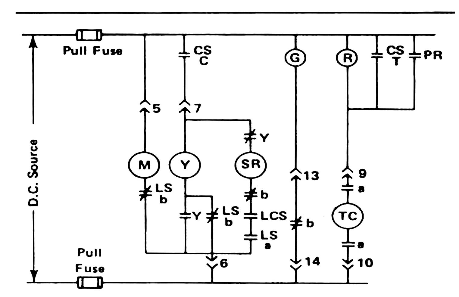
Understanding the Basics of a Wiring Diagram
A wiring diagram is an essential document that every electrician needs to understand. It shows a schematic way of how all the different wires, components and devices are connected together to provide an electrical system. This includes switches, relays, motors, circuit breakers, wire harnesses and other control devices. By understanding the wiring diagram, electricians can identify where power is going, short-circuits, and other related problems.
Understandably, most people are intimidated by the sheer complexity of a wiring diagram. It may look like a jumbled mess of wires and symbols on paper, but it does have a logical structure and deep meaning. That’s why it’s important to get familiar with the basics when it comes to reading a wiring diagram. With this knowledge, you can recognize the symbols, interpret the lines, and figure out what the diagram is trying to tell you.
Recognizing the Symbols Used in a Wiring Diagram
Most wiring diagrams use standardized symbols to represent the various components of the system. The main symbol will be a rectangle, which represents the equipment being connected. Inside the rectangle, you’ll find different shapes and lines that designate the type and size of the component. Here are some common symbols used in wiring diagrams:
- Circle – represents a switch or button
- Solid lines – represent electrical connections and wires
- Dash lines – indicate physical connections only
- Dotted lines – are used to link multiple components
Interpreting the Lines Found in a Wiring Diagram
Once you understand the symbols used in wiring diagrams, the next step is to learn how to interpret the lines. The lines in a wiring diagram represent the various wires and connections between components. The thicker lines indicate larger gauge wires, and the thinner lines are smaller gauge wires. Most wiring diagrams also use special symbols to indicate connections, such as a jumper wire or a branch. All these lines help electricians see how the components fit together and how they should be connected.
Understanding the Color Coding System in Wiring Diagrams
Wiring diagrams often contain color codes that tell electricians what type of wire each connection uses. The National Electrical Code assigns different colors to the negative, neutral, and ground wires. Typically, black indicates the negative wire, white is the neutral wire, and green is the ground wire. Other colors are assigned for other purposes, such as red for a hot wire and blue for a car battery wire.
Conclusion
Learning the basics of wiring diagrams is essential for any electrician. With this knowledge, you can identify components, interpret lines, and understand the color coding system used in wiring diagrams. By mastering the diagram, electricians can quickly diagnose and repair any issue in an electrical system.

Ldr Circuit Diagram Build Electronic Circuits

How To Read A Schematic Learn Sparkfun Com

Sample Basic Wiring Diagram For Small Engines Using Magneto Ignition With Points Isavetractors

Wiring Diagrams Explained How To Read Upmation
Circuit Breaker Wiring Diagram And Connection Procedure Etechnog
Circuit Breaker Wiring Diagram And Connection Procedure Etechnog

Trailer Wiring Diagrams Etrailer Com

Mastering Single Line And Wiring Diagrams Using Circuit Breaker For Mv Power Factor Correction Eep

How To Read Car Wiring Diagrams Short Beginners Version Rustyautos Com

Relay Type Automatic Voltage Ilizer Circuit Diagram

Developing A Wiring Diagram Circuit 1

The Control Circuit Wiring Diagram Scientific

Simple Led Circuit Diagram

Circuit Breaker Control Schematic Explained

How To Read Electrical Schematics Circuit Basics

How To Convert A Basic Wiring Diagram Plc Program Realpars

How To Read Car Wiring Diagrams Short Beginners Version Rustyautos Com

Circuit Diagram Of The Main Distribution Board Scientific

Circuit Diagram And Its Components Explanation With Symbols


