Understanding All You Need to Know about 12 Volt Relay Circuit Diagrams
Electrical wiring is an essential part of any electrical system, and the ability to understand how to read and interpret a circuit diagram is important for successful completion of any electrical project. A 12-volt relay circuit diagram is used to connect two circuits with a 12-volt current, allowing for switching between them without having to constantly adjust the power supply. This article will explain how to interpret and use these diagrams to benefit your projects.
A 12-volt relay circuit diagram represents a switching device in the form of an integrated circuit. Relays are a valuable control method used in many different types of wiring projects, but understanding how they work and how to read a circuit diagram to make the most of their features can be daunting. A 12-volt relay circuit diagram offers the opportunity to use the power of this device to achieve the desired results.
What is a 12-Volt Relay Circuit Diagram?
A 12-volt relay circuit diagram is a schematic representation of the physical components of a particular type of electrical circuit. It is used to represent the relationship between the various components of the circuit and to determine the amount of current, voltage or resistance in each part. This diagram allows an individual to visualize the components and the way they interact to provide the desired outcome. By looking at the diagram, one can identify the different parts of the circuit and how they interact with each other, enabling the user to determine whether the circuit is functioning as intended or not.
Reading a 12-Volt Relay Circuit Diagram
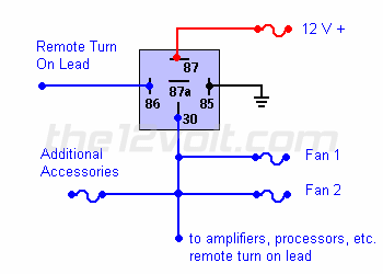
The diagram typically includes symbols representing each component and how it connects to the other parts. The most common parts are usually labeled, and the physical components can be identified by the abbreviations accompanying them. Depending on the complexity of the circuit and its components, the diagram may be divided into sections for easier comprehension. For example, the section for the relay will include the contacts, the coils, and the type of coil used.
In addition to symbols, diagrams may also contain arrows to indicate the flow of current from one component to another. Additionally, notes may be included on the diagram that provide additional information about the parts or their placement. It is important to thoroughly read these additional instructions as they can help identify any issues or inconsistencies. By following these instructions, one can ensure that all components work together as intended and that the entire circuit functions as expected.
Applications of 12-Volt Relay Circuit Diagrams
12-volt relay circuit diagrams have a variety of uses. These diagrams can be used to create and control circuits for home automation projects, robots, solar energy systems and other electrical projects. In some cases, a 12-volt relay circuit diagram can also be used to create a security system. By connecting the appropriate components, a user can create a system that will detect when someone enters the area and immediately alert authorities if necessary.
Relay circuit diagrams are also useful for troubleshooting electronic circuits. By examining the diagram and examining each component, the technician can isolate any problems and quickly repair the issue. Additionally, the diagrams can be used to check if a device is operating properly and if it meets safety standards.
Benefits of Understanding 12-Volt Relay Circuit Diagrams
Learning to read and interpret a 12-volt relay circuit diagram is extremely beneficial for electrical projects of all sizes. Through the use of diagrams, an individual can easily build and control electrical systems, diagnose any problems that may arise and ensure that all components are functioning as intended. With this knowledge, individuals can confidently create electrical circuits and safely troubleshoot any issues that may arise.

Latching Relay Circuit Schematic

Push On Off Relay Switch

Switching 12vdc Led Indicator Lamp Through Relay Ledultiplexing Arduino Forum

How To Hook Up A 12v Relay Module General Electronics Arduino Forum

Circuit Diagram The Above Figure Shows Of Scientific

1 To 20 Minute Timer Circuit Using 555 Ic

Relay Case How To Use Relays And Why You Need Them Onallcylinders

Switching Two Alternate Loads On Off With Ic 555 Homemade Circuit Projects

Special Applications With Spdt Relays

12v Time Delay Relay Circuit Electroschematics Com

Relay Bypass Tj Generation

12 24 Volt Dc 1500 Amp Series Parallel Solenoid Relay

Relay Type Automatic Voltage Ilizer Circuit Diagram
How To Make A Simple Circuit With 12v Relay That Switches Off And On Again After 20 Seconds Automatically Quora

12v Relay Based Timer Switch Circuit Using Bc547 Transistor

How To Build A Heavy Duty 12 Volt Flasher Unit Detailed Description Using Circuit Schematic Bright Hub Engineering

Automotive Relay Diagram

4 Pin Relay Wiring Diagram Vs 5

Esp32 Relay Tutorial
